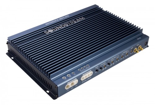
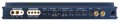
REF2.370
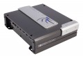
Reference Series 370w Class A/B 2ch. Amplifier
| RMS Power @ 4Ω, 14.4V | 110 x 2 |
| RMS Power @ 2Ω, 14.4V | 185 x 2 |
| RMS Power @ 4Ω Bridged, 14.4V | 370 x 1 |
- Descripción
- Specifications
- Support
Descripción
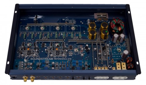
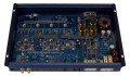
Optimized Component Layout
Every semiconductor component necessary for Reference amplifiers were painstakingly arranged on an original circuit board design for optimal stereo separation, noise induction resistance, and superior performance. Only low tolerance components are used in the signal path; <1% resistors & <5% capacitors.
Differential RCA Inputs & Signal Paths
Differential signaling in an amplifier is transmitting the audio signal by two separate paths using paired traces. The technique of sending the audio signal by these differential pairs increases resistance to external interferences & electromagnetic noises. Additionally, differential feedback from the speaker terminals surrounds the power-amp stages, resulting in uncolored sound reproduction & elimination of ground loops.
Triple Darlington Audio Output Stages
Three sets of transistors drive one another for increased current gain. Pre-Driver Transistors feed Driver Transistors, which feed the final Output Stage Transistors. General amplifier technology employs only Driver Transistors and the Output Transistors. Every stage powering the next reduces load stresses, increases current gain, and ultimately avoids added distortion.
Individually Sequenced Output Stage
The biasing of each channel of a Reference amplifier is independently sequenced, ensuring proper operating conditions. The consistency of current and voltage flow optimizes sound quality by eliminating current or voltage spikes.
Separated Capacitor Current Paths
Power supply & pre-amp capacitance bank charging and discharging paths travel separate from each other. Separated traces prevents rail switching spikes and ground loop traces that could cause unwanted distortion. Additionally, the low ESR capacitance banks compensate power supply ripple currents.
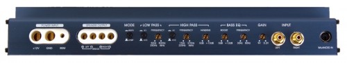
Hawkins Boost Control
Select Reference amplifiers feature a variable Hawkins bass boost circuitry, developed by Soundstream nearly 20 years ago. The variable frequency bass boost is set with up to 10dB gain. Simultaneously, a 12dB subsonic crossover trails the boost frequency. So, the Hawkins circuitry cuts off rapidly below the boost frequency, preventing damage to speakers or woofers that could have been damaged by the overdriven, nearly inaudible lower frequencies.
Additional Key Features
- Sequenced Delays Eliminate Residual Power-Up/Power-Down Pops
- Stout 2 Oz. Copper Traces Effortlessly Transfer High Volume Internal Current
- Individually Regulated Preamp/Crossover Power Supplies Ensure Signal Purity
- 2-Ohm Stereo, 4-Ohm Bridged Stable Class A/B Full Range
- Accepts Balanced Signal from BLT – Balanced Line Transmitter
- Continuously Variable 12dB Crossovers
- Isolated 4ga Power and 8ga Speaker Terminals
| SPECIFICATIONS | REF2.370 |
|---|---|
| Channels | 2 |
| RMS Power @ 4Ω, 14.4V | 2 x 110 |
| RMS Power @ 2Ω, 14.4V | 2 x 185 |
| RMS Power @ 4Ω Bridged, 14.4V | 1 x 370 |
| Total Harmonic Distortion (4Ω power) | 0.02% |
| Frequency Response | 15-50kHz |
| Signal-to-Noise Ratio (4Ω power) | 102dB |
| Damping Factor (100Hz, 4Ω) | >3000 |
| Dimensions: 2.25"h x 9.875" |
13.5" |
| Ch. 1&2 HPF/Hawkins/Subsonic (12dB Slope / 0-10dB Hawkins Boost) |
15-240Hz or 275-4.1kHz |
| Channels 1&2 LPF (12dB Slope) | 50-210Hz or 820-4kHz |
| External Fuse Required | 40 A |
